| NeuroScript MovAlyzeR Help | Send comments on this topic. |
Glossary Item Box
| NeuroScript MovAlyzeR Help | Send comments on this topic. |
Image Processing
MovAlyzeR can be used to process scanned handwriting images. These settings can be used to control the processing parameters.
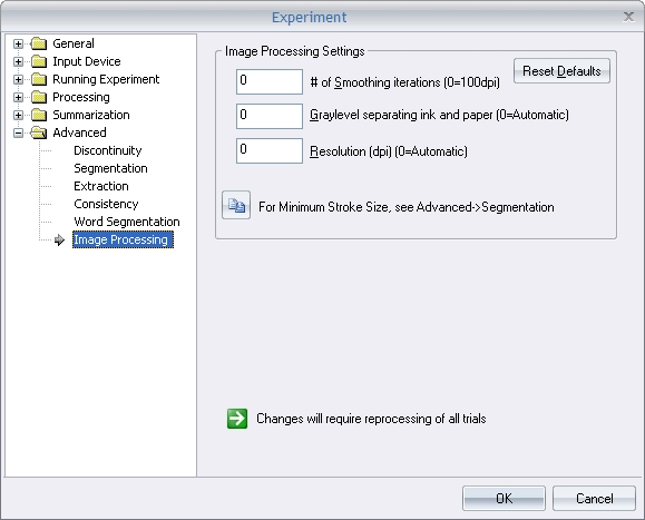
Gray level separating ink and paper
The image is inverted so that the paper background will low gray levels of 0 (displayed as black) and the ink high gray-levels up to 255 (displayed as white). Pixels will be made white (representing ink) or black (representing background) depending upon whether their gray levels are above or below this gray-level threshold, respectively. Lower threshold will interpret more of the image as ink and less as background.
Threshold = 0 means MovAlyzeR will determine automatically an optimum threshold level. Otsu's method is used to estimate the threshold level.
Otsu, N., "A Threshold Selection Method from Gray-Level Histograms," IEEE Transactions on Systems, Man, and Cybernetics, Vol. 9, No. 1, 1979, pp. 62-66.
After this gray-level thresholding all ink traces that touch the outside boundaries of the image will be removed entirely as they are assumed to belong to the handwriting lines above and below the scanned handwriting lines. Artifacts will arise if those lines touch the scanned line(s).
Resolution
The scanning resolution of the image being processed.
Fot eg: If the image was scanned at a resolution of 300 dpi (dots per inch), then a image width of 600 px would mean a width of 2 inches.
#Smoothing iterations before thinning
Images with isolated pixels or coarse ink traces may need blurring by 1 or more smoothing iterations. One smoothing iteration consists of iteratively placing a 3 x 3 pixel window on each pixel and adjusting that pixel to the majority of the 8 surrounding pixels.
Subsequently the Safe Point Thinning Algorithm (Naccache & Shingal, 1984) is applied. This algorithm produces a one-pixel wide skeleton following the center lien of the ink trace. The algorithm provides also a local line width estimate which is color coded and output as the z-value in the handwriting movement HWR file.
Fork pixels are identified by pixel connected to more than 2 pixels. End pixels are identified by pixels connected to less than 2 pixels. (only white pixels are considered, representing ink). The pixels around fork and end pixels are discarded.
Minimum segment length
Segments smaller than this size will be discarded when converting the image to a raw handwriting movement HWR file.
Also, long straight segments (e.g., from guide lines) with near horizontal orientation are discarded as well.
Each segment, defined as a string bounded by end or fork points are arbitrarily sequenced from left to right and output to a raw handwriting movement HWR file. Sequence, direction, and velocity of the strokes in the raw handwriting movement HWR file are arbitrary.
The numerical extracted data file shows for each segment:
Trial -- Sequential replication number within a condition
Segment -- Arbitrary segment sequence number
AverageThickness -- Line thickness (cm), estimated from the number of average local thickness for each segment pixel, i.e. the number of skeletonization passes before that pixel was isolated.
HorizontalStart -- Horizontal position of the lower-left side of a segment relative to the lower left of the image (cm).
VerticalStart -- Vertical position of the lower-left side of a segment relative to the lower left of the image (cm).
HorizonalSize -- Horizontal segment size (cm), which is estimated by the difference between minimum and maximum vertical pixel position.
VerticalSize -- Vertical segment size (cm) which is estimated by the difference between maximum and minimum horizontal pixel position, after deskewing the average slant of all segments to vertical.
RoadLength -- Segment length (cm), estimated from the number of pixels
Slant -- Segment slant (rad), which is estimated by the orientation of the line minimizing the sum of the squared perpendicular distances of all pixels to the line through the point of gravity. The method is suggested by Lansky et al. (1987) for the calculation of the perceptual orientation of a dot cluster. Because horizontal segments do not contribute to the slant only slant values between plus and minus 45 degrees from vertical are used.
StraightnessRelError -- Relative straigtness error, which is estimated by the root mean square distance of all pixels in the segment to the regression line (Slant) divided by the segment length (TraceLength).
LoopArea -- Normalized or relative surface of a loop. The surface of a loop is divided by taking the square root and dividing by the segment length. E.g., a circle yields 1/(2*sqrt(pi)) = 0.28, independently of its size.
Archedness -- Relative size of garlands and arcades, which is the square root of the area enclosed by a segment and a line connecting begin and end pixel. Archedness is only adopted for segments that do not form a loop and have slants between plus and minus 45 degrees from horizontal. Arcades result in a positive archedness while garlands result in a negative archedness.
GarlandRelSize -- Relative size of garlands = Archedness if positive
ArcadeRelSize -- Relative size of arcades = Archedness if negative
ArchedFrequency -- Frequency of garlands and arcades per sample (calculated across sample) *
GarlandFrequency -- Frequency of garlands per sample (calculated across sample) *
ArcadeFrequency -- Frequency of arcades per sample (calculated across sample) *
(*) The number of arches, garlands, arcades is used to estimate the SD, based on the binomial distribution using the normal approximation. So if the total number of segments is N and the number of arches is n then the probability of a segment being an arch is n/N=p. A binomial distribution with large N (and n) has an expected mean=Np and an expected SD=sqrt(Np(1-p))=sqrt(n(1-n/N))
| See Also |
NSHelp: Processing Time functions | Processing Segmentation Settings
© NeuroScript LLC. All Rights Reserved.